Logic Structures & Mathematical Reasoning
Application of Logic
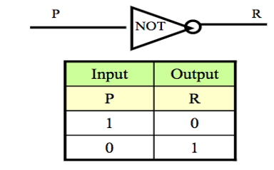
NOT-Gate
A NOT-gate (or inverter) is a circuit with one input and one output signal. If the input signal is 1, the output signal is 0. Conversely, if the input signal is 0, then the output signal is 1.
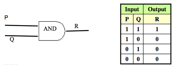
AND-Gate
An AND-gate is a circuit with two input signals and one output signal. If both input signals are 1, the output signal is 1. Otherwise the output signal is 0. Symbolic representation & Input/Output Table is shown below.
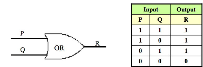
OR-Gate
An OR-gate is a circuit with two input signals and one output signal. If both input signals are 0, then the output signal is 0. Otherwise, the output signal is 1.
Symbolic representation & Input/Output Table is shown below.
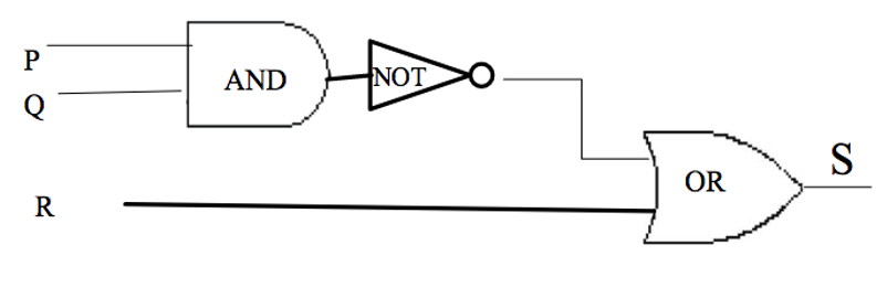
Combinatorial Circuit:
A Combinational Circuit is a compound circuit consisting of the basic logic gates such as NOT, AND, OR.
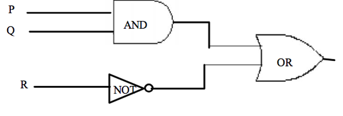
Exercise and Solution
Determine the output for a given input:
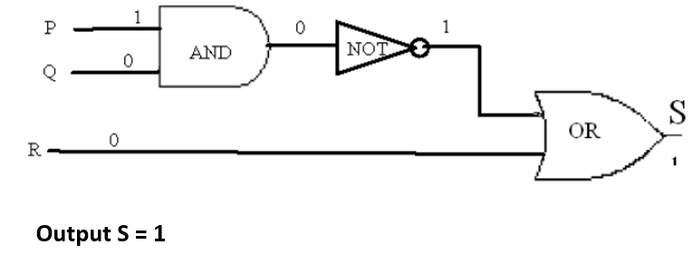
Indicate the output of the circuit below when the input signals are P = 1, Q = 0 and R = 0. See the diagram below:
Solution:
For more details, please contact me here.
Date of last modification: 2024